I helped this elf solve puzzles the other day.
         o
        / \
       (*_*)   Hey I'm the elf I'm green
         |
       \---/
         |
        / \
In exchange, they'd like to send me a great wealth of realtime data.
A treasure trove of knowledge
They said they'd throw in a free t-shirt if I can process the data using programmable hardware and write it in Hardcaml.
100% cotton
I was able to clarify a few things before the elf returned to the north pole:
Q: How will this data be transferred to me?
A: UDP packets over IP on Ethernet
Q: Could you be more specific?
A: Not right now. Take these and get started.
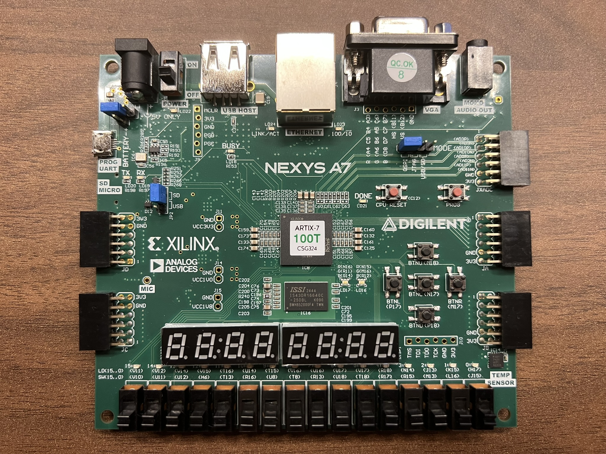
The elf handed me an FPGA development board.
And a diagram.
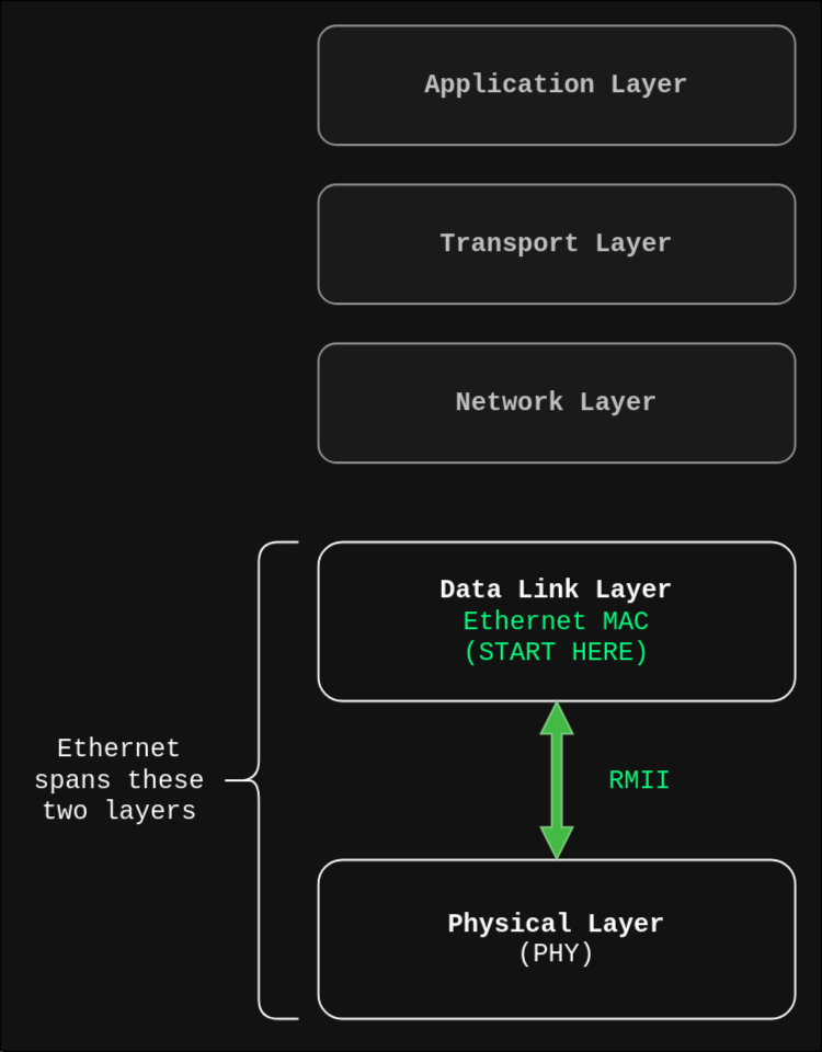
Seems reasonable enough. We'll start from the bottom.
An ethernet cable is plugged into the wall of the igloo. It appears to be a typical copper twisted pair cable. On the jacket it says "Cat 9"... Sure, ok. I take the other end and plug it into the FPGA board.
The elf's diagram seems to suggest that the physical layer is already being handled. How? I flip over the board and see this little chip almost directly below the RJ-45 jack.
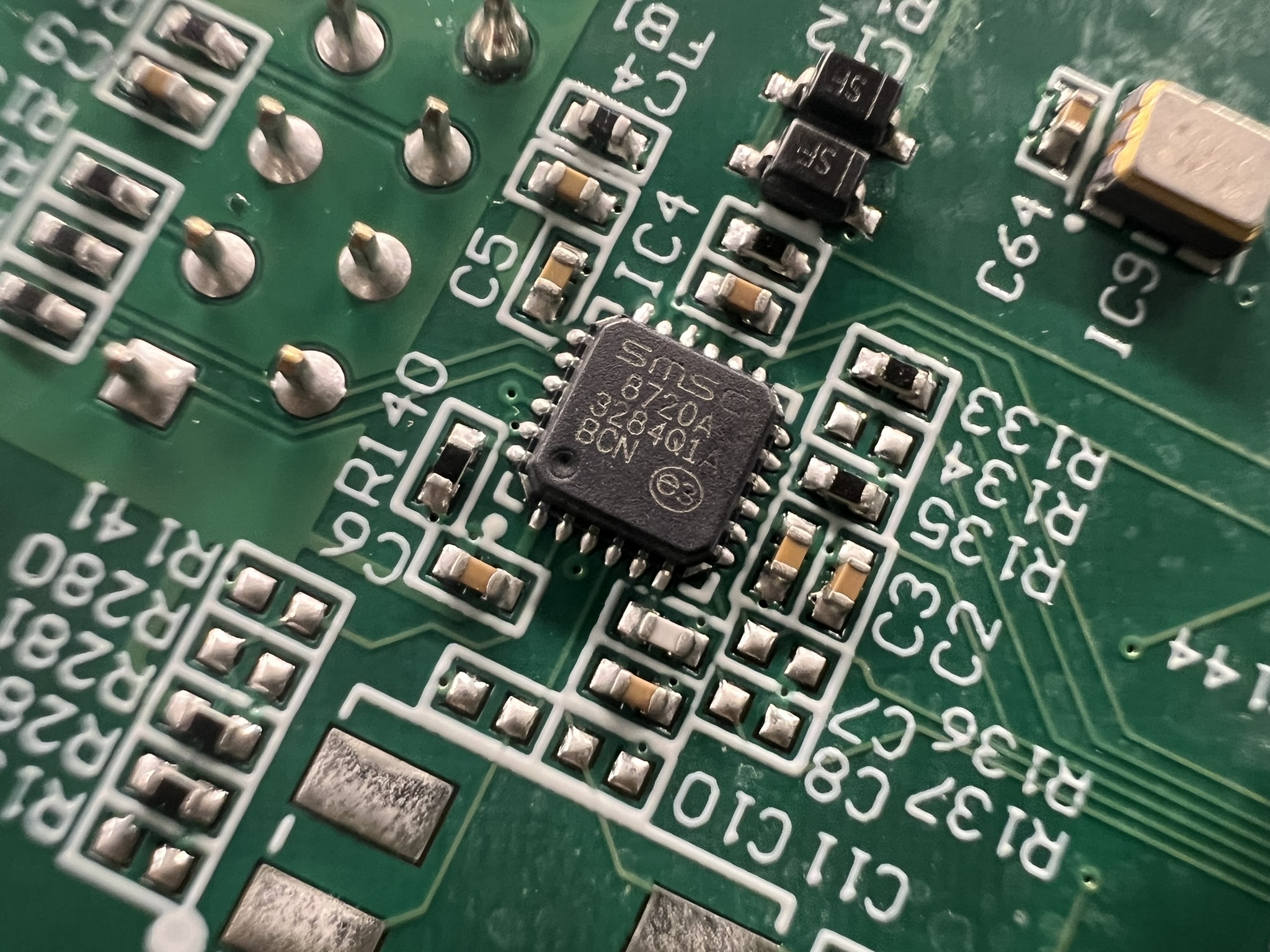
After a brief visit to the datasheet section of my local public library, I found the datasheet for SMSC's LAN8720A Physical Layer Transceiver (PHY).
Looks like the PHY does a few things:
Digital to Analog Conversion (and vice-versa): Convert between analog signals on the wire and digital bitstreams inside the chip. The signal on the wire depends on the medium (e.g. copper or optical fiber). The PHY digitally communicates with the FPGA over the RMII interface. More on that later.
Encoding / Clock Recovery: Inside of an FPGA, the clock is distributed throughout the fabric, so different components can use the same clock to synchronize and coordinate with each other. But the clock signal is not transmitted along with the data on the Ethernet cable. So how does the receiver determine bit boundaries? If the transmitter sends 11111111, how does the receiver know how many bits there are? Even if the two parties agree on a clock frequency beforehand, variations in temperature, cable length, and manufacturing may result in slight differences. Fortunately, it can be possible to figure out where the clock is if the data is encoded in a particular way.
A good encoding should include many transitions, regardless of what the data is. The receiver can lose track of the clock whenever there are long sequences of 1s or 0s, so the transitions help keep them in sync. A simple example of an encoding that does this well is Manchester Encoding. A 1 is encoded as a transition from low to high, and a 0 is encoded as a transition from high to low.
Additionally, the signal should spend roughly equal time in the low and high states. Ethernet signals pass through transformers, which block DC signals and pass AC signals. In other words, they will pass changes in the signal but the signal will disappear if there is a long run of constant voltage. If the average signal remains centered between the low and the high values, it's easy for the receiver to differentiate low and high.
The specific encoding that this PHY uses is MLT-3 encoding.
Auto-Negotiation: Depending on the available hardware, Ethernet can operate at a wide range of speeds. The particular PHY on my dev board can operate at either 10 or 100Mbps. The PHY will negotiate the fastest mutually supported speed with the hardware it's connected to. The rest of the hardware here in the igloo can operate at at least 100Mbps, so if everything goes right, that's the speed I should be operating at.
I am forever grateful that the PHY handles all that. My work will remain fully digital, starting with communication with the PHY over RMII. The component that handles this communication is the Ethernet MAC.
Part 2: Ethernet MAC